Simulating Shallow DOF As A Postprocess Simulating Shallow DOF As A Postprocess
 Many times photographs and videos have portions that are blurry and others that are sharp even when nothing is moving.
For the most part, how blurry something looks in the image depends on how far in front of behind
it is from the part that in focus. Images that have only a small partion in focus are said to have a shallow depth of field.
I am familiar with how to simulate lens blur in a ray tracing scenario but I wanted to add this effect
to any simple polygon or billboard engine.
Many times photographs and videos have portions that are blurry and others that are sharp even when nothing is moving.
For the most part, how blurry something looks in the image depends on how far in front of behind
it is from the part that in focus. Images that have only a small partion in focus are said to have a shallow depth of field.
I am familiar with how to simulate lens blur in a ray tracing scenario but I wanted to add this effect
to any simple polygon or billboard engine.
My approach was simple. Given a bunch of objects in front of the camera, the object that is in focus gets drawn unmodified whereas as the other objects get blurred based on their relative distance. Being that photography is a hobby of mine, I wanted the actual amount of blurring as well as the quality of the blurring to be somewhat related to how much a real lens would blur. Limitations aside I was pleased with the result.
Please note that this mostly a high-level doc. Although source code is provided, the ideas in this doc apply to many programming environments. Some of the things in this doc can be handled quickly by hardware acceleration(ie OpenGL, Direct3D) but I will not touch these subjects. Also, I am just starting to learn about LaTeX so this doc has math in it.
 To the right is a setup I carefully constructed :) and photographed with a camera lens combo that would result
in a shallow depth of field. Click on either guy to focus on him.
To the right is a setup I carefully constructed :) and photographed with a camera lens combo that would result
in a shallow depth of field. Click on either guy to focus on him.
I then took individual pictures so that I can composite them. The trick is figuring out how much to blur each one to get it to look like the photographs.
 +
+
 +
+
 +
+
 =
=
We can simply blur each layer based on how far away from the focal point is like this "blur_amount := abs(layer_pos - focus_pos)*scale". However I want a more accurate blur amount. We are going to simulate a very simple camera.
Simulating our eyes or an an actual lens is absolute insanity. Instead we are going to use something called the thin lens formula which approximates a simple lens like a magnifying glass. The formula states: \[ \frac{1}{s1} + \frac{1}{s2} = \frac{1}{f} \]
Out of curiosity, I wrote a ray tracing simulation to compare how the thin lens formula compare to ray tracing a spherical lens. The simulation can be seen here. The green boxes are s1 and s2 as computed using the thin lens formula. The yellow lines are ray traced lines simulating yellow light through a glass lens. The lens geometry was computed using the lens maker's formula Notice that the rays don't all converge at the same spot. This is due to spherical abberations. The thin lens formula is quite close espcially at smaller apertures.
Although the thins lens formula allows us to compute the relative position fo the focal plane, this is not very useful when writing
games or simulations. We want to be able to explicitly control what the camera is focusing on.
We need a way to compute the position of the lens, given how far an object is from the image plane. The problem showh below. Move the lens
around to try and focus on the point 'T'.
You'll notice that the point can be focused one of two ways. When lens is all the way to the right, the lens is in "macro" mode or "close focus" mode. We can ignore this
for now and always want position where s1 < s2. Here
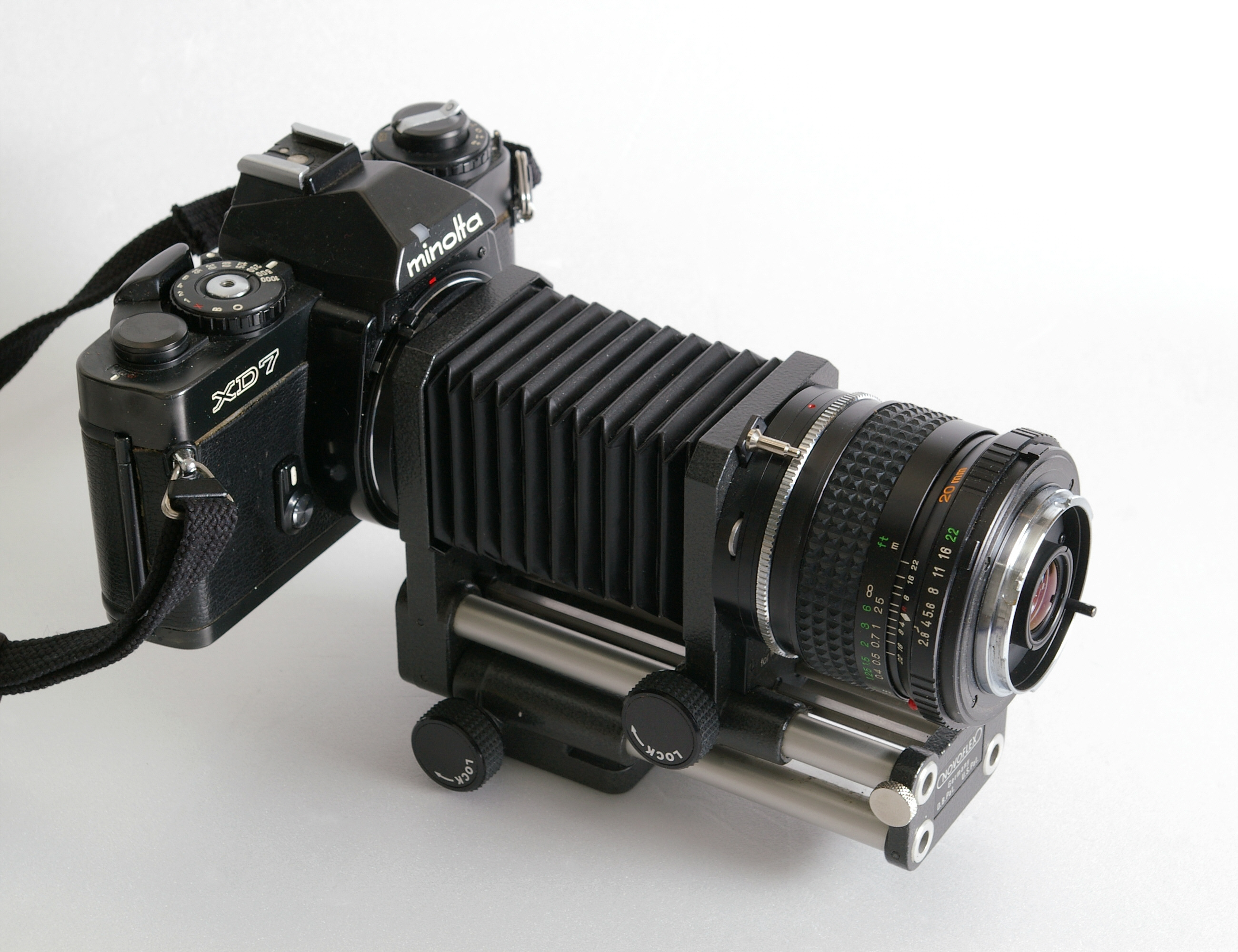
is a camera set up for macro shots. Notice how far forward the lens is!
If we let d be the total distance from the image plane to our target, we can solve for "s1" because we know that \[ \begin{align} s1 + s2 = d \\ s2 = d - s1 \end{align} \] Substituing this equation for s2 into the thin lens formula and solving for s1 yields a quadratic equation. We can use the quadratic equation solve for s1. Remember that the quadratic equation can have 2 solution. This lines up with are observation that we can focus the camera one of two ways. The algebra is shown step by step on the right. \[ -\frac{1}{d}s1^2 + s1 - f = 0 \\\\ \] Click here to see the algebra step by step.
Notice that if d < 4*f, the discriminator will be imaginary. When d = 4*f, s1 = s2 = 2f. At this point the image will plane will have to move back in order to get a focused image and thus are in "macro mode". We will ignore "macro mode" and consider this our focus limit.
Because this was a bit math heavy, here is the code to the "focus" function focus the lens in order to solidify things. The full listing is in DOFCam.js
    /**
     * Move the lens relative to the image plane such that param "p"  is "in focus".
     *
     * this.pos is the image pane position on the number line
     * p is the object position on the number.
     *
     * Note that we assume the objects is always "in front" of the camera
     *
     * The function returns whether or not the camera was able to focus on "p"
     *
     */
    DOFCam.prototype.focus = function(p) {
        var d = Math.abs(p - this.pos)

        if( d < 4*this.focalLen ) {
            this.s1 = 2*this.focalLen
            this.s2 = 2*this.focalLen

            return false
        }

        var a = -1/d
        var b = 1
        var c = -this.focalLen
        var disc = b*b - 4*a*c

        //previous check should prevent this but just in case!
        if( disc < 0 ) {
            this.s1 = 2*this.focalLen
            this.s2 = 2*this.focalLen

            return false
        }

        this.s1 = (-b + Math.sqrt(disc))/(2*a)
        this.s2 = (-b - Math.sqrt(disc))/(2*a)

        //we know for a fact we don't want to operate in "macro" mode
        //so if s1 less than s2 swap!
        if( this.s1 > this.s2 ) {
            var t = this.s1
            this.s1 = this.s2
            this.s2 = t
        }

        return true
    }
Now that we can focus our camera we can talk about the portions of the image that are out of focus. The hole that the light enters into the camera is called the aperture. How blurry out of focus things look depends on how big this aperture is. We assume the aperture is circular and it's diameter is usually expressed as the ratio of the lens focal length. The aperture is a theoritical number. These ratios are called f numbers and are a conveniant measure for a bunch of reasons. For example, the photographs in the beginning of this doc were shot at f/1.8. This makes our theoritical aperture = 85mm/1.8 ~ 47mm.
 |
 |
[1] \[\begin{align}
\frac{C}{L - S} &= \frac{A}{S} \\
C &= \frac{A}{S}(L - S)
\end{align} \]
\[\begin{align}
\frac{C}{L - S} &= \frac{A}{S} \\
C &= \frac{A}{S}(L - S)
\end{align} \]
|
[2] \[\begin{align}
\frac{C}{S - L} &= \frac{A}{S} \\
C &= \frac{A}{S}(S - L)
\end{align} \]
\[\begin{align}
\frac{C}{S - L} &= \frac{A}{S} \\
C &= \frac{A}{S}(S - L)
\end{align} \]
|
Both (L - S) and (S - L) can be replaced by |S - L|. Here is the final function
    DOFCam.prototype.radiusOfConfusion = function(s1) {
        var la = 0.5 * this.focalLen/this.fNum

        if( s1 == 0 ) {
            return Infinity
        }

        if( s1 > 0 ) {
            return la/s1*Math.abs(this.s1 - s1)
        }

        if( s1 < 0 ) {
            return la/s1*Math.abs(this.s1 - s1) //arithmetic works out
        }
    }
This function returns the radius of the cof in real units. Millimeters in our case. To conver to pixels you need the scale the width relative to the image plan size. For 35mm cameras, the image plane width is 35mm. The photos on this doc were taken by a Nikon D90 which has a 24mm image plane width.
    DOFCam.prototype.blurRadiusPixels = function(cofr, imageWidth) {
        return Math.abs(cofr)/this.imgPlaneWidth*imageWidth
    }
We finally have all the parts to reconstruct our example. All we need is a way to blur our layers. Blurring is topic on it's own. It also happens to be quite expensive to blur things without hardware acceleration. Notice in the first pictures that the blurred portions of the image are quite smooth. There is a kind of blur called a Gaussian blur that is usually the go to guy when a smooth blur is wanted. However Gaussian blurs are pretty expensive to perform in pure Javascript. Instead we will use a much less smooth but much faster blur called a "box" blur. The blurring will be done with the box blur from StackBlur.js.
We also need to know the precise distances of all our layers to the camera. I chose the edge of the notebook
as theh scene's origin. Below is a picture of the actual scena I photographed. Notice the camera and figures.
I mesured the figures' positions relative to the edege of the notepad.
Move the lens focal point back and forth to see how much to blur to apply to each layer. Notice how minutely
the lens actually moves. The blurring is done using .
The pure JS blurring is note quite fast enough to do in real time so the blurring only updates when you let go of
the mouse.

|
|
|
Blurring things in realtime can be a bit expensive. For example, I couldn't find a pure-js blur that fast enough to do the above example in real time. For this reason we wish to limit the amount of layers that we have to blur. You can imagine if you are drawing polygons, sprite particles or sprite billboards, the distinct number of things drawn might number in the thousands. What we want to do is group things then blur the group all at once. In order to do this, let's have a look at our circle of confusion function to get a feel for its shape.
Here I have graphed our cof function with the camera focused at different points.
The kink at the focal point is due to the "abs" function we are using. If you allow the left side to dip towards -infinity you will see a smooth curve. It looks like the curve goes towards -infinity towards the 0 (it does). It looks like there is limit when go towards +infinity. As x gets huge, you can see that x's real image distance will converge to the focal length. This means the limit is: cam.radiusOfConfusion(cam.focalLen)
I would always have a layer for things really far away(the infinity layer) and another for things in focus. If the focal point is sufficiently far, than the blur layer will have a blur radius if < 0.5 pixels in which there is no need for an infinity layer. Exactly how we group our objects depends on how many blur layers we have. I would bunch most of them around the focal point since that is where the user will most likely be looking.
 [2]
[2]  [3]
[3] 
 Pic [1] is in an in focus picture of the LED on my monitor. Pic [2] is the same LED but purposely brought way out of focus.
Notice that enough light makes it to the LED's circle of confusion to still show up as bright green. Pic [3] is pic [1] blurred
with a Gaussian blur. Notice how quickly the green spreads out. This happens because the green highlight's brightness is "cut off"
at 255 green in the JPG data. If we were properly store the brightness of the LED without cutting off, we would need to store
a value of 16,000 instead of just 255 (at least according to my camera's light meter).
This "cuttong off" makes it hard to set up scenes like this one using just a
pure Gaussian blur. We can get a more convincing blur a bunch of ways.
Pic [1] is in an in focus picture of the LED on my monitor. Pic [2] is the same LED but purposely brought way out of focus.
Notice that enough light makes it to the LED's circle of confusion to still show up as bright green. Pic [3] is pic [1] blurred
with a Gaussian blur. Notice how quickly the green spreads out. This happens because the green highlight's brightness is "cut off"
at 255 green in the JPG data. If we were properly store the brightness of the LED without cutting off, we would need to store
a value of 16,000 instead of just 255 (at least according to my camera's light meter).
This "cuttong off" makes it hard to set up scenes like this one using just a
pure Gaussian blur. We can get a more convincing blur a bunch of ways.
We could store the image as an HDRI image so that highlight's bridghtness can be properly represented and blur correctly. This is quite expensive though since many graphics packages and environments do not support HDRI images. Also HDRI images are pain to work with.
When performing the blur, we can set a threshold and choose a really high value for pixels past this value. This will allow the pixels to influence neighboring more than the 100% green pixels can. This "bloom" effect is kind of a pseudo HDRI and is useful for other things as well.
We can set up a sprite to put in the place of the highlight and set the size and opacity accordingly. This will allow much control over the appearance of the highlights but would be a pain to manage.

Here are some places on consulted while playing around with this lens stuff. Not all of it is relevant but all are interesting.